Technology
I had the good fortune to be trained as a machinist as a teenager by an extremely talented tool and die maker that was a friend of the family. When I later entered Yale, my sister (studying there as a musician) introduced me to Gus Lienhard at the Yale Medical School, who in turn introduced me to Fred Richards.
Fred was constantly building instruments and was at the time was developing crystallographic "flow cells" that could examine the properties of proteins in their crystalline state. He was soon joined at Yale by Hal Wyckoff and i continued to build a wide range of hardware over the ensuing tears for both Fred and Hal. in later years, I continued to build equipment and instrumentation and retain an interest to this day.
Fred was constantly building instruments and was at the time was developing crystallographic "flow cells" that could examine the properties of proteins in their crystalline state. He was soon joined at Yale by Hal Wyckoff and i continued to build a wide range of hardware over the ensuing tears for both Fred and Hal. in later years, I continued to build equipment and instrumentation and retain an interest to this day.

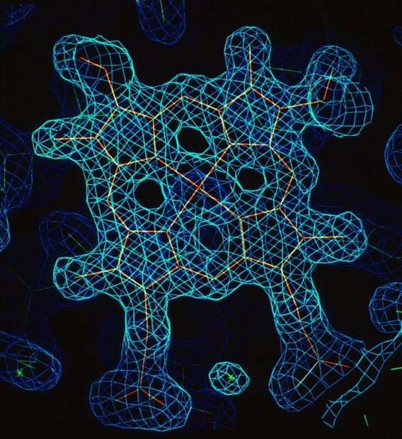
Structure determination in the early days of protein crystallography was a process that typically proceeded in stages where electron density maps were determined at increasingly high resolution, finally allowing a detailed trace of the polypeptide backbone. Often, physical models were built of sectioned electron density maps at low resolution to define molecular boundaries and establish secondary structural features.
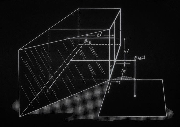
Richards Optical Comparator - aka Richards Box

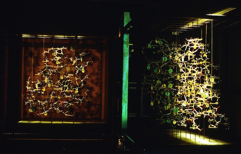
Model building in the early days of protein crystallography was a tedious process that involved trying to trace a polypeptide chain across contoured sections of an electron density map. I recall Fred coming into the lab one day and showing me his Leica with its split-image rangefinder. This is the solution he said, and promptly left for a sabbatical at Oxford where he built "Fred's Folly", the first Richards Box. The Richards box was in fact a quantum leap forward in building 1cm/A wire Kendrew models of protein structures.
I built the first installation at Yale as well as additional versions at UCSD and UAZ.
Advances in computer graphics made the Richards box obsolete for protein crystallography. It was subsequently discovered that the Richards box principle had been used in 19th century stage shows to portray ghosts.
Protein Crystallization

While a graduate student at UCSD I developed a free interface diffusion method for protein crystallization. This method differs from most others in common use as it creates an initial and transient supersaturating condition that can promote the growth of a few nucleii that can subsequently grow to form large crystals.
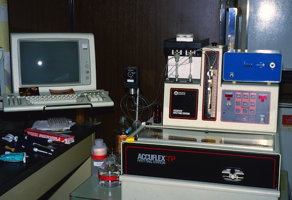
in 1986, Pat Weber and Jane Cox at DuPont CR&D developed the first automated robotic system for protein crystallization using the hanging drop format. This instrument was commercialized by ICN Micromedics.
The original instrument deposited drops containing a protein solution together with buffer and other additives (usually using binary buffer systems for pH control) onto cover slips that were then manually flipped over onto hanging drop chambers.
The original instrument deposited drops containing a protein solution together with buffer and other additives (usually using binary buffer systems for pH control) onto cover slips that were then manually flipped over onto hanging drop chambers.
At DuPont CR&D, we also participated in several experiments on the Space Shuttle to study the effects of microgravity on the formation of protein crystals.
Protein Crystals
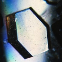
Lysozyme
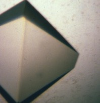
PCD
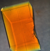
Cytochrome C-prime
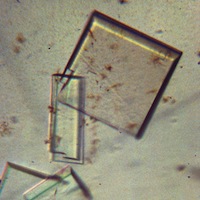
Streptavidin
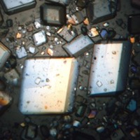
Subtilisin
Data Collection Technology

Picker made one of the earliest 4-circle diffractometers for crystallography. At Yale we upgraded an early mechanical unit to drive angles and record data using IBM punch cards. Angular readout on early units used geared contact encoders. I also used a later generation instrument at UAZ that took input from a DEC PDP8.
At UCSD we used a Hilger Watts 4-circle diffractometer that encoded angles using a Fresnel-fringe detection system. Although theoretically more reliable than the mechanical encoders on the Picker machines, instabilities in the electronics created a different set of problems. Output was on punched paper tape, which required a pretreatment run through a toothbrush labyrinth in order to be reliably read by the available tape readers.
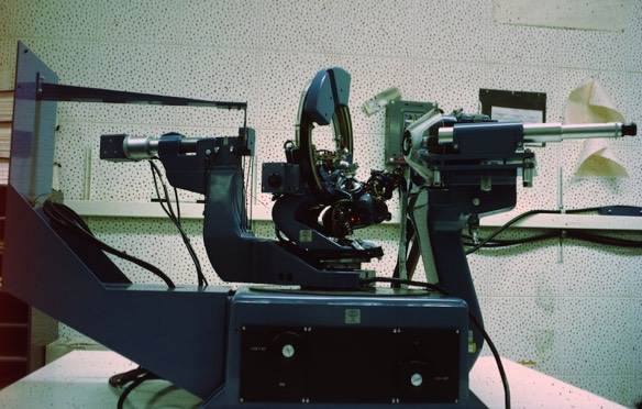
By the early eighties, 4-circle machines like the Huber incorporated digital pulse drive motors and optical encoders that made the systems quite reliable. At that point, many labs had been using oscillation cameras and film scanners to collect data, which was more efficient that diffractometry for large unit cells like viruses. This in turn motivated the investigation of particle detection systems used in high-energy physics for X-ray applications. The Xentronics detector shown was an early example with single phi axis spindle rotation.
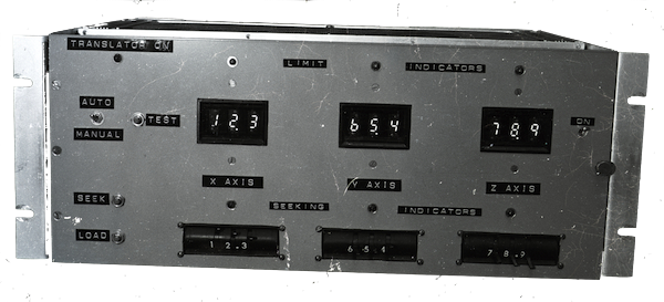
Automatic Coordinate Hunting Engine
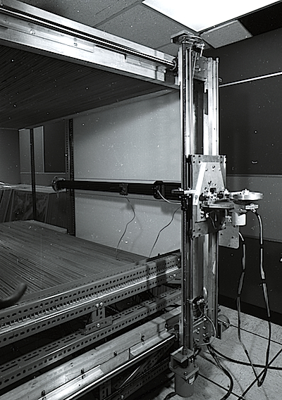
Measuring accurate coordinates from a Kendrew wire model produced in a Richards box was difficult. This difficulty created a substantial impediment to the efficient application of crystallographic refinement methods to proteins. Steve Freer and Richard Alden, working in Joe Kraut's lab at UCSD, were early pioneers in protein structure refinement, and motivated me in turn to come up with a better way to measure coordinates from Kendrew models.
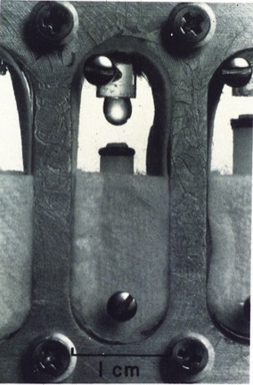
I teamed up with David Fehr in 1971, a friend from the Physics Department at UCSD, and together we built a device for protein coordinate measurement that used first generation TTL circuitry and digital pulse motors to drive a small light for superposition on reflected Kendrew model images. The device proved much faster and more accurate than previous methods and produced lower R-factor input structures on refinement initiation.
The ACHE was rendered obsolete for protein coordinate measurement with the advent of interactive computer graphics. Nevertheless, the device was resurrected after several years in storage by Russell Dolittle, who found it useful to derive atomic coordinates from physical molecular models of fibrinogen.
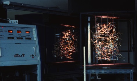
AHCE with Richards Box at UCSD circa 1971
Electronic Area Detectors
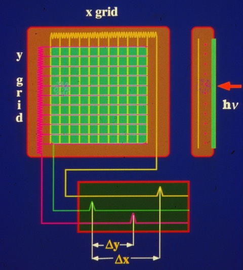
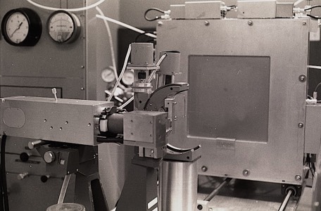
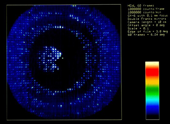
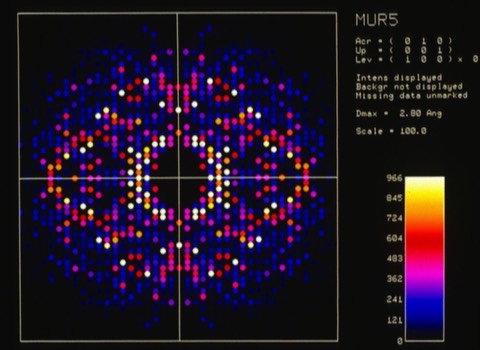
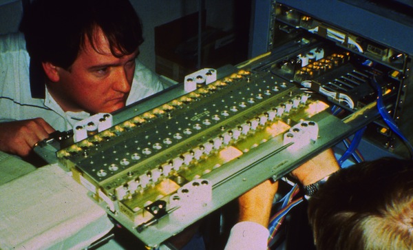
X-ray area detectors based on designs originally developed for high energy physics experiments were becoming commercially available by the early eighties. The detector basically incorporated an x-y wire array forming a grid-based ionization detector. Wires output ionization signals through x-axis and y-axis delay lines to determine the xy position of scattered X-ray photons. Translating this information into assignable structure factor intensities required the ability to predict the location on the detector where diffraction spots would occur.
Xoung Nguyen-huu at UCSD developed one of the first X-ray area detectors that used a grid-based ionization detector and delay lines to determine the position of scattered X-ray photons. This instrument became the basis for the commercial instruments produced by Area Detector Systems Corporation (ADSC). I collaborated with Xuong to collect data on the UCSD system in the late seventies.
The Xentronics 2D detector was developed slightly later by Ron Burns in collaboration with protein crystallographers at Harvard.
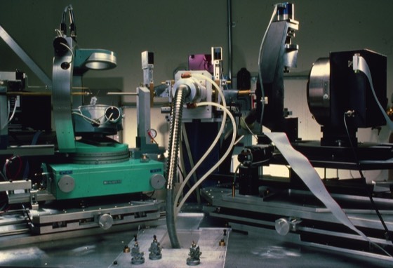
Later Xentronics instruments incorporated a phi + kappa axis goniometer mount that gave more flexibility in crystal mounting and data collection strategy.
Subsequently, at Genex, we became an early adopter of the Xentronics detector system. Under Andy Howard's lead, we undertook development of a comprehensive data analysis and reduction system (XENGEN) which subsequently became widely used throughout industry and academia.
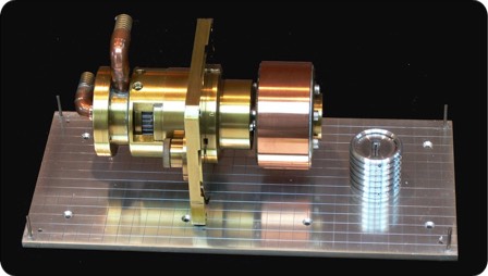
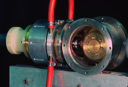
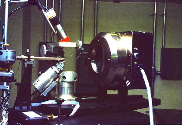
Rotating Anode X-Ray Generator
I built a rotating anode X-ray generator (parts of which are shown here) while a faculty member at UAZ. Rotating anode design presents some interesting engineering challenges. One is the requirement to maintain a rotating seal into the ultra-high vacuum environment that is required for X-ray generation. At the time of the this design (around 1980), ferrofluidic seals were becoming commercially available and offered an excellent solution to the rotating seal problem.