UCSD Steam Car
As a graduate student with Joe Kraut at UCSD, I usually worked late into the night, often monitoring “automated” X-ray data collection on our Hilger-Watts 4-circle diffractometer. Stanley Miller, a Professor of Chemistry at UCSD who was famous for his origin of life experiments, occupied the other side of the third floor of Bonner Hall and so we often chatted. Stanley was an avid steam enthusiast, a subject where I also had an interest, particularly as it related to the early history of the automobile. At the time, in addition to pursuing my PhD, I was building various pieces of equipment for the UCSD X-ray lab, including a Richards box and an automated device to allow the precision measurement protein model coordinates. In order to do this, Joe had persuaded the powers in the Physics Department to let me use the Physics graduate student machine shop, which was overall fairly well equipped (In those days, it was still judged important that experimental physicists be able to build their own apparatus in the machine shop).
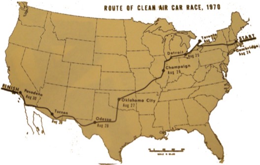
In the course of our discussions, Stanly noted an upcoming Clean Air Car Race that was being sponsored jointly by MIT and CalTech and that was to occur in August 1970, about nine months from the date of our discussion, as I recall. The race was to begin at MIT in Boston on August 24, 1970 and run to Caltech in Pasedana by August 30. We decided to build a car to enter the competition. Stanley was the project leader, I was responsible for the technical implementation, and we recruited Rodney Burton from the UCSD engineering department to help us with the serious engineering issues. Subsequently, we recruited several additional undergraduates and friends to help in the project.
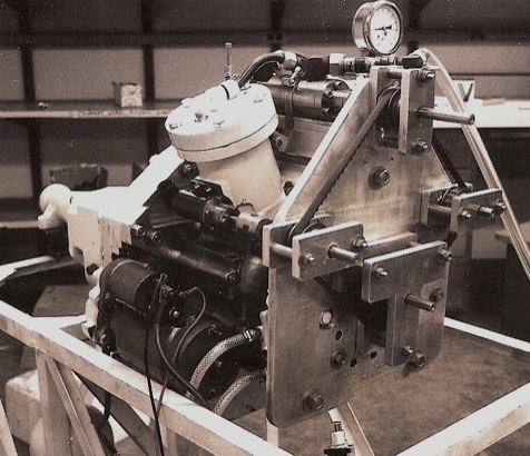
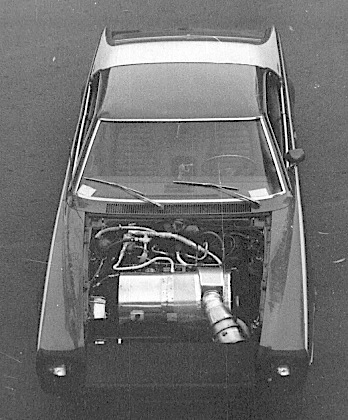
The first rolling chassis with header-tube boiler and rotary cutoff valve.
In the event, we decided that a power plant with an output of 75 horsepower would be sufficient to achieve our performance objectives that were centered on a running speed of 50 mph on the highway. The major design constraint was the desire to operate a closed-loop system that required condensing the low pressure steam exhaust from the engine. This in turn required a large condenser and also created a significant parasitic load required to drive the condenser cooling fan.
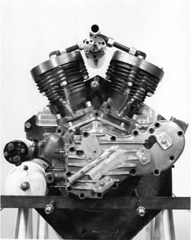
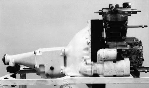
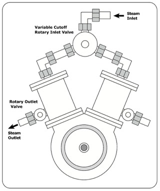
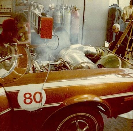
The target steam pressure (600-800 psi) indicated that a displacement of approximately 80 cubic inches would be sufficient. We consequently decided to build the engine around the lower end of a Harley Davidson V2 motorcycle engine since we were unequipped to build a complete crankshaft-connecting rod assembly. At he same time, there were torque limitations on the Harley crankshaft assembly, so we decided to connect the output of the V2 engine to a conventional auto transmission to reduce lower end torque loads and achieve added efficiency associated with running the engine over a limited RPM range. Also, the uniflow design required a conventional starter to insure correct engine rotation direction.
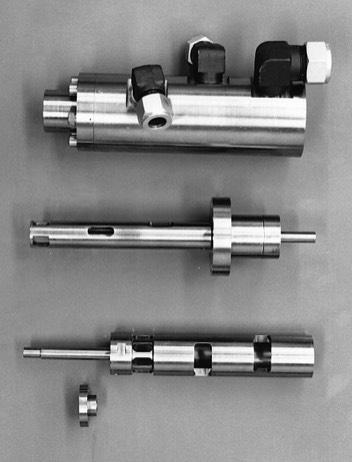
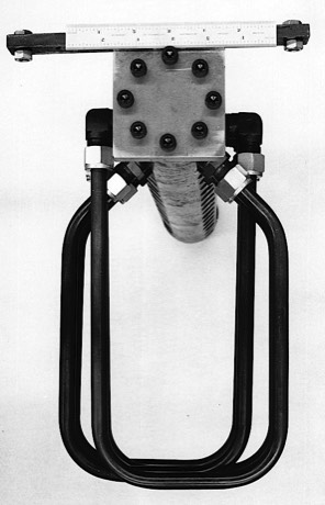
The engine was a uniflow design with a variable cutoff rotary inlet valve and two rotary outlet valves. Initially we modified the original Harley cylinder barrels that were fitted with new heads. However, the original cast iron cylinders made connection of the output rotary valves difficult, so the Harley cylinders were replaced with machined steel units. The initial variable cutoff valve design used high nickel alloy steel to minimize potential problems with thermal expansion. This was a tough material to machine and did not work as planned in practice. The valve was replaced by a simpler alternative design by the time of the race.
The initial boiler was a header-tube design assembled using chrome-moly tubing and high pressure fittings. The boiler was fired using a liquid propane burner system, but ultimately did not produce sufficient steam output. We decided to refocus efforts when we had a gas ignition problem leading to a small explosion that blew apart the boiler firebox.
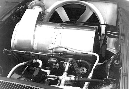
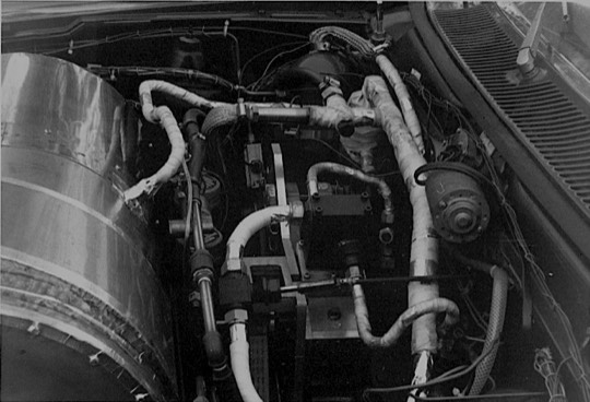
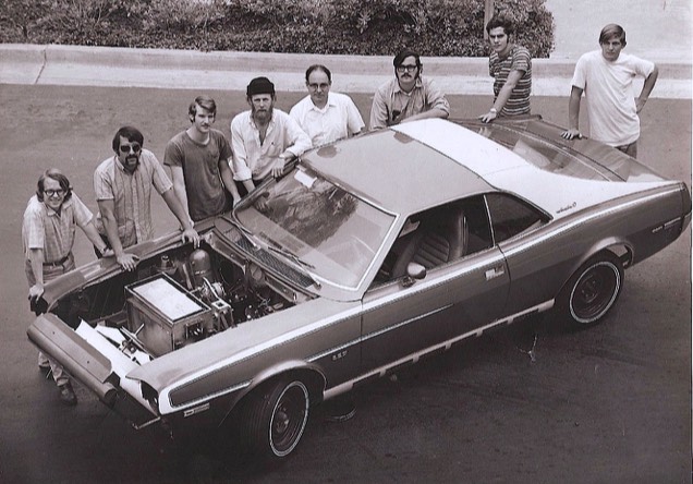
Owing to Stanley Miller’s efforts, we were able to obtain an engineless Javelin chassis from American Motors as the rolling platform for our team car. Initial tests of the car with installed systems (using the header tube boiler) revealed several issues, so that a major effort was undertaken to develop electrical sensors and controls that would allow the burner-boiler system to respond to changes in demand occurring during stop-start situations. This was complicated, since unlike an internal combustion engine, a lot of heat energy was stored in the boiler tubes that would translate to excess stream pressure and temperature if flow was suddenly shut off. Venting directly to the condenser, which was modified from a large truck radiator, was not an option owing to the large pressure differential.
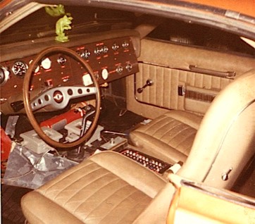
We ran out of time during the final assembly and test phase of the car, so we decided to install the newly developed control system components in the staging area garage at MIT, where many teams were planning to arrive several days early to prepare for the race. General Motors had graciously loaned all of teams green Chevrolet station wagons as support vehicles, and we packed up all of control system components in that vehicle and sent two of the team to drive across country from San Diego. We followed a day later hauling the nearly completed UCSD Steam Javelin on a trailer.
About half way across Arizona, we spotted a green vehicle with an orange logo on the side well off the road in the desert brush. A few miles down the road we realized that the car was most likely ours. In fact it was, and most of our control system components had been scattered around the desert as a result. A backup team rescued the drivers and the parts while we continued to MIT.
The scene in the MIT garage was frantic. Evidently we were not the only ones making last minute adjustments and modifications. However, since we had lost some intended control modules, we ended up with makeshift mechanical controls that required two people to run the car. We were able to get the car moving under its own power outside of Boston, but ultimately only ran it for only a few miles at a max speed around 30 mph in fear of irreversibly breaking something. We put the car back on the trailer and followed the convoy through all of the stops back across the country. We ran the car locally for a few laps during the trip including some dynamometer tests at the General Motors research facility in Detroit.